MMR40 Chassis Work (Con’t)
MMR40 Chassis Work (Con’t)
I was able to get a little more chassis work done on the MMR-40. Here is what the faceplate looks like now. I’m still debating on whether to put in a jack for headphones on the front. This will end up with a laminated photo overlay for a nice looking finish.

MMR-40 Faceplate
Ace Hardware had some nylon screws an nuts that I used to mount the PC board. This prevents any shorts that might occur due to some traces being really close to the screw holes.

Mounting Hardware
So the board is bolted to the perfboard, with the controls sticking out the front panel just enough to tighten the nut on the microphone jack to add some stability.

MMR40 Mounted in the chassis
Here is a wide view of the board and external wiring. All connections to the board are on headers, so it may easily be unplugged to work on it out of the chassis. I haven’t tied up all of the wires yet, as it’s still a work in progress.
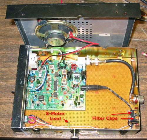
MMR-40 Overhead view
I used some 0.1 inch computer headers for the disconnects. I was able to scrounge some connectors from old computers around here, but I’d really like to find some to buy, in order to use them more in the future.
MMR-40 Header Disconnects
The back panel is where power comes in via the original jack for the CB chassis. The original SO-239 antenna socket is also used. I didn’t have any BNC connectors for RG-58 right now, so I have used some RG-59. I’ll probably change it out later, as the RG-58 is more flexible. The RG-59 is 75 ohm cable, but that short length shouldn’t matter.

MMR40 Back Panel
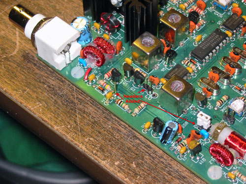
And here is the back side of the fron panel. The KD1JV Digital dial is mounted on the left, and connects to the Local Oscillator Pad with a 4.7pf capacitor in line. The digital dial requires that the BFO frequency be programmed in. This was done by tapping on to U5 pin 7 with the 4.7 pf capacitor. That detuned the BFO a bit, so I tuned it back until it sounded right again, then jumped the programming pads on the back of the dial momentarily to put it into programming mode. After selecting mode “C”, I pressed the function button for 1 second to put it back into frequency mode. Finally, the BFO was readjusted to its original state, once the load from the counter was removed again.

MMR-40 Front Panel


Comments
Post a Comment