W7ZOI Universal Transmitter MkII
W7ZOI Universal Transmitter MkII
I have named this project the PieceKit DX-6.0 in respect to the original Heathkit DX-60 Transmitter.
The intent is to build a version of W7ZOI's Universal Transmitter MKII that was published in the April, 2006 issue of QST magazine. After adding a few extra features, I would like to put this in a small cabinet that looks a lot like the Classic Heathkit DX-60 transmitter. But this will be a DX-6.0 because it is QRP.
A parts kit was ordered from KangaUS. And some extra parts including the cabinet was bought locally at Circuit Specialists.
The oscillator section was built manhatten style on a small piece of the circuit board that was included in the parts kit.
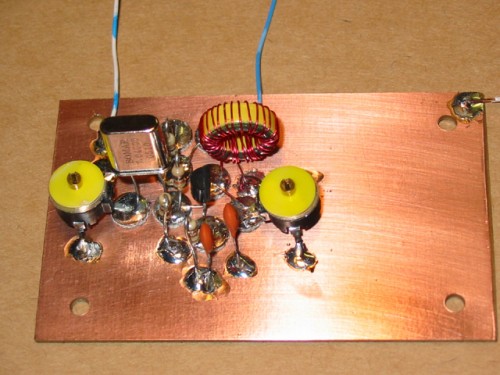
Next, the RF Chain was built


and the two were connected together for testing.

The Oscillator was outputting about 3 volts peak-to-peak at the top of the drive adjustment potentiometer R17.

The Driver stage was putting out about 5.6 volts peak-to-peak at the input of T3

The Final Stage was outputting about 42 volts peak-to-peak into a 50 ohm load.
42 vpp / 2 = 21 volts peak.
21 volts peak * 0.707 = 14.847 volts RMS
(14.847 ^ 2) / 50 = 4.4 watts

The RF section appeared to work OK, so now the Keying sections were built on a two more pieces of circuit board.
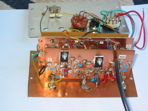
After testing, all four boards were soldered in a vertical position on a
base of circuit board, using bent terminal lugs to secure the boards.
Some provisions were made in an attempt to gain VXO control and multiple
crystal switching, but these are still under development.
Here is the rear view, with the RF Chain at the bottom, the Control in the middle and at the top left, and the oscillator section at the top right.

And a front view, showing the Oscillator board on the left, control on the right, and the front panel connections, with crystal switching, vxo control and power control.

A cabinet was purchased from Circuit Specialists in Mesa Arizona. This is a small cabinet that was originally a tan color. I got some Hunter Green paint from Home Depot, and painted it to look kind of like Heathkit Green.

Photoshop was used to create a Heathkit like appearance for the front panel. This was printed on photographic paper by Walmart, and I intend to glue it to the front panel and cover it with a clear acrylic cover.

Testing reveals that I need to look into electronic switching for the crystal switching, maybe some 2N7000 Fets to do the switching and reduce stray capacitance from the long wires to the front panel. In addition, the VXO capacitor has little effect as it is now configured. Perhaps I need to look into using a varicap diode to do the VXO control, again to reduce stray capacitance from the wires to the front panel. More on that as the project continues


Comments
Post a Comment