Building the NorcalQRP SMD Dummy Load
Building the NorcalQRP SMD Dummy Load
This device is a 5-watt dummy load that is pretty unique in that all of the load resistors, as well as the diode detector parts are surface mount devices. It is marketed as a learning tool to give people practice at soldering surface mount components. NorcalQRP is the club that distributed the kits.

Construction started with application solder flux from a Flux Pen I got from Frys Electronics. This was followed by application of a dab of the solder paste I ordered from Cash Olson’s Site. It comes in a small syringe. Just squeeze out a small amount onto each solder pad. It tends to look like a very small Hersheys Kiss Chocolate when you have the right amount.

The next step was to place all of the tiny parts onto the board. Good lighting from an overhead lamp, and magnifying goggles help here. I wet the tip of a toothpick and used the surface tension to pick up the parts and place them on the board. Once in place, they stick there pretty good, because the paste is very sticky.

It was hard to tell the anode from the cathode on the surface mount 1N5711 diode. There is a stripe on one end, but it's pretty hard to see.

So I dug out the PC Microscope I had purchased on Ebay in anticipation of this event. It takes nice clear photos up very close. Now it's easy to see the stripe.

Once all of the parts were placed, I set the board onto an old electric skillet. With the temperature set to about 225 degrees F, I let the board sit for about 30 seconds or so. I began to see the paste change color slightly. At that point, I turned on the embossing gun that my wife had purchased at a hobby store for me. This is like a small hot air gun. It gets hot enough to melt the solder, but doesn't blow so much that it moves the tiny parts. About another 30 to 45 seconds went by as I slowly moved the gun back and forth above the components maybe 1-1/2 or 2 inches over them. When I saw the solder melt, the parts just sort of lined themselves up on the pads, and settled into place. I kept the gun moving for maybe another 10 seconds, then turned it off.

After turning off the embossing gun, I waited about another 30 seconds to allow the board to slowly cool off back to the 225 degree point. Then I removed the board. After letting the board cool to near room temperature, I repeated the process on the reverse side (the board has components on both sides). The skillet temperature doesn't hurt the components that rest against it, and the heat from the embossing gun seems to affect only the side facing up, for the short period it is used.
Once the board cooled off again, I examined the solder joints from multiple angles, looking for defects under my magnifying goggles. Finding no defects, I marked and drilled the enclosure for it, and installed the connectors and board into the enclosure. The connector on the left top is the diode detector output, while the connector on the left bottom is simply an RF Tap, so you can scope the signal being applied to the dummy load. Of course, the input BNC is on the right.

Next, I manufactured a cable to connect the output of the diode detector to a digital multimeter. This is how you read the power being absorbed in the dummy load. I soldered an rca plug on one end of a piece of small coax. The other end was stripped and connected to a couple pieces of larger speaker wire, to be more durable for plugging/unplugging into a multimeter.

After applying heat shrink and banana plugs, this is the result

I ran into some trouble while calibrating the unit. I was using my Kenwood TS-480 at low power to check the frequency response of the detector. I had the Accuprobe hooked up as well to the RF Tap point (might as well get two jobs done at the same time).
When I got to six meters, everything stopped working, both the dummy load detector and the accuprobe. I was thinking that maybe the extra cable connected to the RF tap point was throwing the impedance off, and I started isolating things down. At one point I even suspected the BNC connector attached to the board. Anyway, I ended up unsoldering the connectors and running various tests. I found that the 1n5711 surface mount diode, as well as the detector diode in the Accuprobe were blown.
I replaced them both with some old germanium diodes I had laying around.Starting through the tests again,this time with the accuprobe connected with just two rca plugs soldered back to back, I ran into trouble. When I got to six meters, I got the same results, blown diodes.
So I ordered some replacement diodes from Ebay and Mouser. After installing them, I figured I better find out what the radio does at six meters to blow out the diodes. I hooked the radio up into a 100 watt dummy load, and put the scope across its output. All through the HF bands, I was seeing a spike in RF when I would first key up. I suspected that was the problem, but they weren't really big enough spikes to blow the diodes. When I got to six meters, the waveform filled the scope's screen! The radio was putting out 100 watts on six meters only!
As it turns out, the radio has separate adjustments for 6 meter power and HF power. After discovering this, I set the six-meter power to 5 watts, and finished my testing. I put all of the results into an Excel Spreadsheet, and made graphs and tables that were printed up and glued to dummy load, and covered with packing tape.
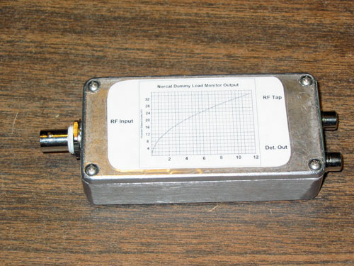
And here is the Chart:

I am now convinced that I like working with surface mount projects more than conventional through-the-hole components. It is actually less work, less mess and generally a better looking project.


Comments
Post a Comment