Building the Accuprobe
Building the Accuprobe
The accuprobe is a kit put out by the North Texas QRP Club . It is an enhanced RF Probe that allows measurements down to around 50 millivolts RMS, or about 50 microwatts. It accomplishes this by using a schottky diode as the detector, and a matching schottky diode in the feedback loop of an op amp that follows the detector. The amount of feedback is proportional to the amount that the schottky diode detector conducts, and so it compensates for the non-linear conduction of the detector diode at very low levels.
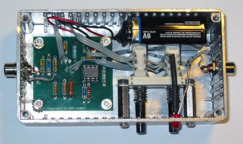
The construction of the Accuprobe was straightforward. There are no surface mount components, so you just simply solder the parts in the correct holes. The opportunity for originality comes in the packaging. The Nortex instructions illustrate installation into an altoids tin. I like my equipment in a more substantial enclosure, so I chose a cast aluminum box.
I used RCA connectors for the RF input and the DC output to the digital multimeter. I found a couple of pushbutton switches from an old stereo in my junkbox that seemed to fit well. It was better than I expected, as the battery is a snug fit behind the switches, so it requires nothing else to hold it in place. I also added an led to indicate when power was applied, so there would be less chance of running the battery down by accident.
The real challenge came from my desire to build an external probe for the device, rather than having it be permanently connected to the case. Following N5ESE's idea for an RF Probe, I started by disassembling a ball point pen
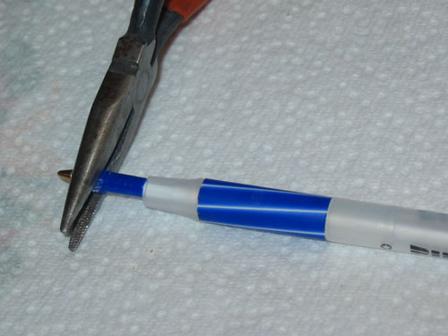

Next, I fashioned a device to hold the probe tip out of some single sided circuit board and a dremmel tool. I found that it needed to be narrower at the tip, because this particular pen got narrower there

I used a dremmel tool to cut the end off of a safety pin to use for the probe tip, and soldered it to the circuit board.


The inner conductor of the coax was soldered to the tip, and the shield was soldered to the larger piece of copper trace on the circuit board. A second wire with an alligator clip was also soldered to the shield connection.

After pushing the circuit board up through the pen body, I used hot melt glue in the tip and the end where the wires exit to make it solid.

Then, after soldering an RCA connector on the other end of the coax, the probe was complete.

During testing of the probe, it became apparent that the long ground lead was throwing off the readings at some frequencies. I built a second probe, but this time I made a slot in the shield side of the circuit board, just after the point where the shield is soldered on. That way, we don't have an antenna sticking up in the air on the shield side. In addition, I made the ground lead shorter, and it exits near the tip, rather than the far end of the probe. This seems to work much better.
I don't have any construction photos of the second probe, but you can see the finished product here

The other major problem I ran into was due to my lack of knowledge about my Kenwood TS-480 transceiver that I was using to test the probe. I had carefully adjusted the power down to 5 watts on 160 meters, and checked the power on other bands. It seemed that once I had set the power for one band, the other bands followed suite.
So I was going through the test by jumping from band to band, and taking a reading across a NorcalQRP dummy load. Everything was going fine until I got to 6 meters. All of the sudden, the readings fell off dramatically. Going back to the lower bands indicated that their readings had fallen off as well. To make matters worse, the detector output of the NorcalQRP dummy load had fallen off too.
I suspected that the 6-meter output of the radio had somehow destroyed the detector diodes, and I was correct in that. I didn't have any schottky diodes in my junkbox, but I did have a few old germanium diodes. I replaced the bad diodes and started the test again. What could there be about 6-meters that would blow out the diodes?? I thought maybe it had to do with the external probe on the accuprobe messing up the impedance, and causing some sort of spike at 50 mhz. So this time, I tested with a cable directly between the dummy load and the Accuprobe same results.
So I put the project aside for a few days while I ordered some new schottky diodes from a dealer on ebay, and some surface mount 1N5711WS diodes from Mouser to replace the burned out one in the Dummy load detector.
Once I replaced the devices again, I decided to check the output of my radio on my high power dummy load and meter. Lo and behold, I had 5 watts out on all the lower bands, but when I switched to 6-meters, I had 100 watts out! It appears that the TS-480 has a separate setting for 6 meter power, as opposed to the lower band’s power settings sharing a common setting. I set the 6-meter setting to 5 watts and re-ran the tests again, this time without incident.
Using Microsoft Excel to store the results, I ran tests at various power levels to the accuprobe. This made it easy to develop a chart for the High Power setting, and a graph for the Low Power setting. These were printed out and glued to the top and bottom of the Accuprobe box. This is calibrated against my 30 year old Tektronix 453 Scope, so they may be off a little, but are close enough for my purposes.


Comments
Post a Comment